文章目录[隐藏]

原文:https://circuitdigest.com/microcontroller-projects/arduino-cnc-machine-project-code
DIY基于Arduino的CNC绘图机
经过**加拉布兹·约翰保罗(Galabuzi Johnpaul)** 2017年9月5日修改评论:17

CNC机床是计算机数控机床,用于根据送入其控制器单元中的设计程序绘制任何东西或设计任何机械零件。控制器单元可以是计算机或微控制器。CNC机械具有步进电机和伺服电机,可根据进料程序绘制设计图。
在研究了CNC机床之后,我决定使用当地可用的材料制造自己的CNC机床。世界上有这么多的CNC机器,其中一些技术制造复杂,甚至无法正确操作。因此,我决定基于Arduino制造一台最简单的 CNC绘图机。您也可以稍作修改就可以将其用作Arduino CNC绘图机。
这款DIY Arduino CNC机器可以绘制大多数基本形状,文字甚至是卡通。它的操作类似于人手书写的方式。与人类的书写或绘画方式相比,它更快,更准确。查看本教程结尾的演示视频。
构建Arduino CNC机器:
要使CNC绘图机运行,需要3个轴(x轴,y轴和z轴。x轴和y轴协同工作以在普通纸上创建2D图像。这些x和y轴彼此成90度角放置,以使普通表面上的任何点都由给定的x和y值定义;使用z轴将笔抬高并放低到普通纸上。
根据要绘制的图像,计算机将生成适当的坐标,然后通过USB端口将其发送到微控制器。微控制器解释这些坐标,然后控制电动机的位置以创建图像。在这里,我们已使用Arduino作为微控制器来构建此CNC机器。三轴运动由步进电机提供,步进电机将由Arduino电路板控制。如果您是初学者,可以选择如何将[步进电机与Arduino](https://circuitdigest.com/microcontroller-projects/arduino-stepper-motor-control-tutorial#:~:text=The circuit Diagram for the,pin of the Arduino Board.)连接。
因此,让我们开始逐步构建Arduino CNC设备。
您需要什么:
***注意:***就大小和所用材料而言,我的设计在硬件上有很大不同。我找不到旧的DVD驱动器,因此选择了打印机部件。无论使用哪种方式,请确保其具有步进电机。
硬件要求:
- 铝板(710mm x 710mm)
- 旧的HP / Epson打印机。您可以使用旧的计算机DVD驱动器
- 螺栓和螺母
- 有机玻璃
- Arduino UNO
- L293D电机驱动器护罩或Arduino CNC护罩
- 迷你伺服马达
- 一支钢笔


工具:
- 螺丝刀
- 钻头
- 切割工具(钢锯)
- 胶水
- 台式装置
软体:
为了使本机高效运行,请使用以下软件。转到各种网站并下载。
CNC绘图机的底座:
该设备的主体是将机器的所有主要部分支撑在一起的底座,因此机器坚固且便于携带。在此设计中,我们将使用铝来构造基座,因为它轻巧,易于弯曲和切割,并且由于它不会生锈,因此具有良好的光泽外观。
我的底座的设计和尺寸如下所示:

***注意:***所有尺寸均以毫米为单位。
经过所有的弯曲和切割,我能够产生一个非常牢固的基础,如下所示:

X,Y和Z轴的组装:
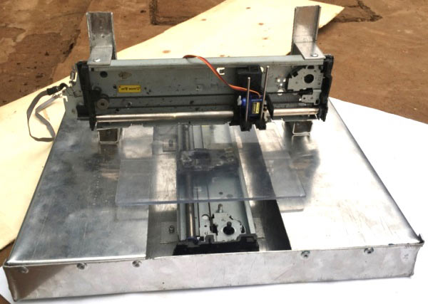
为了制作x和y轴,使用了两个打印机支架。这些部件中的每一个都包含一个步进电机和一个皮带驱动机构,通常用于来回移动墨盒。

对于z轴,使用胶水将微型伺服电机安装在y轴上。该伺服电机用于上下移动笔。应该构造一个良好的支撑机构,以使笔能够自由上下运动。


数控机床绘图平台:
由于本机尺寸巨大,因此该设备可以在A5尺寸的纸张上绘图。因此,我们将从有机玻璃上切出一个A5(148mmx210mm)大小的平台,然后使用胶将其粘贴到x轴移动部件上。

数控机床的接线和电路:
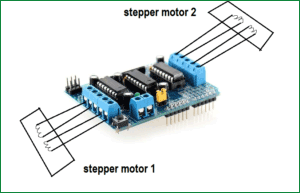
将L293D电机驱动器护罩插入Arduino UNO板上。该防护罩可同时驱动两个步进电机和两个伺服电机。如下图所示连接两个步进电机。由于电动机是双杨型的,因此接地连接应保持未连接状态。这将用作绘图仪机器的Arduino CNC控制器。

还要将小型伺服电机连接到serial1。将7.5V-9V电源连接到电动机驱动器护罩的电源端口。机器现在可以进行测试了。
Arduino CNC机器代码和测试:
首先,我们需要测试步进电机,看看它们是否正确连接。
由于我们使用的是L293D电动机驱动器护罩,因此需要从此处下载AFmotor库。然后将其添加到您的Arduino IDE库文件夹中。确保将其重命名为AFMotor。如果Arduino IDE已打开,则将其关闭并再次打开,然后单击文件->示例-> Adafruit Motor Shield库-> stepper。确保在工具中选择正确的端口和板,然后将代码上传到Arduino板。在步进电机一上应观察到一些运动。
为了测试电动机2,请在下一行中将电动机端口从2更改为1,然后再次上传代码。
#include <AFMotor.h>

// Connect a stepper motor with 48 steps per revolution (7.5 degree)
// to motor port #2 (M3 and M4)
AF_Stepper motor(48, 2);
适用于CNC机器的Arduino代码:

步进电机正确响应后,从下面的“代码”部分复制CNC机器的**Arduino代码,**然后将其上传到Arduino开发板。您可以从下面的链接下载代码。
数控机床的G代码:
G-CODE是我们告诉计算机(CNC)做某事的语言。它基本上是一个包含X,Y和Z坐标的文件。
例如:
G17 G20 G90 G94 G54
G0 Z0.25X-0.5 Y0.
Z0.1
G01 Z0. F5.
G02 X0. Y0.5 I0.5 J0. F2.5
X0.5 Y0. I0. J-0.5
X0. Y-0.5 I-0.5 J0.
X-0.5 Y0. I0. J0.5
G01 Z0.1 F5.
G00 X0. Y0. Z0.25
仅为一个简单的正方形编写G代码可能非常具有挑战性,但是幸运的是,我们拥有一款可以帮助我们生成G代码的软件。该软件称为“ Inkscape ”,可从此处下载。
您可以使用Inkscape生成自己的G代码,我们将在下一部分中进行说明,也可以在互联网上使用随时可用的G代码。
在向您展示如何使用Inkscape生成G代码之前,让我们讨论如何将这些G代码发送到Arduino。使我们能够将G代码发送到Arduino的软件称为处理。
处理IDE以上传G代码:
这个平台将帮助我们将G代码发送到Arduino开发板。为此,您将必须下载GCTRL.PDE文件。
从此处下载GCTRL.pde文件,然后使用Processing IDE打开它

在Processing IDE中打开它后,单击“运行”。出现所有说明的窗口。按键盘上的p。系统将要求您选择一个端口。因此,选择连接Arduino板的端口。我的情况是端口6。
现在按g并浏览到保存G代码的文件夹。选择正确的G代码,然后按Enter。如果一切都正确连接,您应该会看到设备开始在纸上绘图。
如果要终止该过程,只需按x,设备将停止正在执行的任何操作。
如何生成自己的G代码:
我们提到了Inkscape是我们将用于生成G代码的软件。在此示例中,我们将创建一个简单的文本(HELLO WORLD),如下所示。

注意*: Inkscape没有将文件另存为G-CODE的内置方式。因此,您需要安装一个附件*,以将图像导出到G-CODE文件。从此处下载MakerBot Unicorn插件和安装说明。
如果安装成功,请打开Inkscape,转到“文件”菜单,然后单击“文档属性”。首先将尺寸从px更改为mm。同时将宽度和高度减小到90毫米。现在关闭此窗口。正方形显示为绘图区域。这是我们将用来编写文本的区域。
现在,在左侧栏上,单击“创建和编辑文本对象”选项卡。键入文本“ HELLO WORLD ”,并将其放置在正方形的右上角,如下所示。

单击文本,然后选择所需的字体样式。单击应用,然后关闭。
现在单击路径并选择“对象到路径”
现在,您的文本已准备好保存为G-CODE。单击文件->另存为,然后将文件名键入“ hello world”
如下图所示,将文件类型更改为*“ MakerBot Unicon G代码”*。仅在附加组件安装成功时才会显示。最后单击“保存”,然后在弹出窗口中单击“确定”。

您已经生成了G代码,可以使用前面的步骤进行绘制。
GRBL控制器:

使用Inkscape设法生成G代码后,可能有必要查看G代码以确保它在图纸范围内。
该绘图限制在Arduino的CNC代码集在下面示出的行:

如上所示,GRBL控制器中的图像不应超出上述CNC Arduino代码中所示的限制。如果超出了这些限制(例如,朝着X轴的负侧),则将不会绘制负侧的该部分。
在此示例中,x和y值的范围为0mm至40mm。
由于我使用的打印机零件可能会在更大的区域上绘图,因此我将最大值从40mm更改为60mm。
每当使用Inkscape生成G代码时,您都可以先在GRBL程序中打开该G代码,以查看它是否在这些限制之内。如果不在此范围内,则需要在Inkscape中调整图像的大小,直到超出限制为止。
因此,这是在家里使用arduino uno建造CNC绘图仪的最便宜,最简单的方法。尝试一下,在评论中让我们知道,也请查看下面的视频。
/*
 Send GCODE to this Sketch using gctrl.pde https://github.com/damellis/gctrl
 Convert SVG to GCODE with MakerBot Unicorn plugin for Inkscape available here https://github.com/martymcguire/inkscape-unicorn
 Arduino code for this Mini CNC Plotter based on: https://github.com/adidax/mini_cnc_plotter_firmware
*/

#include <Servo.h>
#include <AFMotor.h>

#define LINE_BUFFER_LENGTH 512

char STEP = MICROSTEP ;

// Servo position for Up and Down
const int penZUp = 115;
const int penZDown = 83;

// Servo on PWM pin 10
const int penServoPin =10 ;

// Should be right for DVD steppers, but is not too important here
const int stepsPerRevolution = 48;

// create servo object to control a servo
Servo penServo;

// Initialize steppers for X- and Y-axis using this Arduino pins for the L293D H-bridge
AF_Stepper myStepperY(stepsPerRevolution,1);
AF_Stepper myStepperX(stepsPerRevolution,2);

/* Structures, global variables    */
struct point {
  float x;
  float y;
  float z;
};

// Current position of plothead
struct point actuatorPos;

//  Drawing settings, should be OK
float StepInc = 1;
int StepDelay = 0;
int LineDelay =0;
int penDelay = 50;

// Motor steps to go 1 millimeter.
// Use test sketch to go 100 steps. Measure the length of line.
// Calculate steps per mm. Enter here.
float StepsPerMillimeterX = 100.0;
float StepsPerMillimeterY = 100.0;

// Drawing robot limits, in mm
// OK to start with. Could go up to 50 mm if calibrated well.
float Xmin = 0;
float Xmax = 40;
float Ymin = 0;
float Ymax = 40;
float Zmin = 0;
float Zmax = 1;

float Xpos = Xmin;
float Ypos = Ymin;
float Zpos = Zmax;

// Set to true to get debug output.
boolean verbose = false;

//  Needs to interpret
//  G1 for moving
//  G4 P300 (wait 150ms)
//  M300 S30 (pen down)
//  M300 S50 (pen up)
//  Discard anything with a (
//  Discard any other command!

/**********************
 * void setup() - Initialisations
 ***********************/
void setup() {
  //  Setup

  Serial.begin( 9600 );

  penServo.attach(penServoPin);
  penServo.write(penZUp);
  delay(100);

  // Decrease if necessary
  myStepperX.setSpeed(600);
  myStepperY.setSpeed(600);

  //  Set & move to initial default position
  // TBD

  //  Notifications!!!
  Serial.println("Mini CNC Plotter alive and kicking!");
  Serial.print("X range is from ");
  Serial.print(Xmin);
  Serial.print(" to ");
  Serial.print(Xmax);
  Serial.println(" mm.");
  Serial.print("Y range is from ");
  Serial.print(Ymin);
  Serial.print(" to ");
  Serial.print(Ymax);
  Serial.println(" mm.");
}

/**********************
 * void loop() - Main loop
 ***********************/
void loop()
{

  delay(100);
  char line[ LINE_BUFFER_LENGTH ];
  char c;
  int lineIndex;
  bool lineIsComment, lineSemiColon;

  lineIndex = 0;
  lineSemiColon = false;
  lineIsComment = false;

  while (1) {

    // Serial reception - Mostly from Grbl, added semicolon support
    while ( Serial.available()>0 ) {
      c = Serial.read();
      if (( c == '\n') || (c == '\r') ) {             // End of line reached
        if ( lineIndex > 0 ) {                        // Line is complete. Then execute!
          line[ lineIndex ] = '\0';                   // Terminate string
          if (verbose) {
            Serial.print( "Received : ");
            Serial.println( line );
          }
          processIncomingLine( line, lineIndex );
          lineIndex = 0;
        }
        else {
          // Empty or comment line. Skip block.
        }
        lineIsComment = false;
        lineSemiColon = false;
        Serial.println("ok");
      }
      else {
        if ( (lineIsComment) || (lineSemiColon) ) {   // Throw away all comment characters
          if ( c == ')' )  lineIsComment = false;     // End of comment. Resume line.
        }
        else {
          if ( c <= ' ' ) {                           // Throw away whitepace and control characters
          }
          else if ( c == '/' ) {                    // Block delete not supported. Ignore character.
          }
          else if ( c == '(' ) {                    // Enable comments flag and ignore all characters until ')' or EOL.
            lineIsComment = true;
          }
          else if ( c == ';' ) {
            lineSemiColon = true;
          }
          else if ( lineIndex >= LINE_BUFFER_LENGTH-1 ) {
            Serial.println( "ERROR - lineBuffer overflow" );
            lineIsComment = false;
            lineSemiColon = false;
          }
          else if ( c >= 'a' && c <= 'z' ) {        // Upcase lowercase
            line[ lineIndex++ ] = c-'a'+'A';
          }
          else {
            line[ lineIndex++ ] = c;
          }
        }
      }
    }
  }
}

void processIncomingLine( char* line, int charNB ) {
  int currentIndex = 0;
  char buffer[ 64 ];                                 // Hope that 64 is enough for 1 parameter
  struct point newPos;

  newPos.x = 0.0;
  newPos.y = 0.0;

  //  Needs to interpret
  //  G1 for moving
  //  G4 P300 (wait 150ms)
  //  G1 X60 Y30
  //  G1 X30 Y50
  //  M300 S30 (pen down)
  //  M300 S50 (pen up)
  //  Discard anything with a (
  //  Discard any other command!

  while( currentIndex < charNB ) {
    switch ( line[ currentIndex++ ] ) {              // Select command, if any
    case 'U':
      penUp();
      break;
    case 'D':
      penDown();
      break;
    case 'G':
      buffer[0] = line[ currentIndex++ ];          // /!\ Dirty - Only works with 2 digit commands
      //      buffer[1] = line[ currentIndex++ ];
      //      buffer[2] = '\0';
      buffer[1] = '\0';

      switch ( atoi( buffer ) ){                   // Select G command
      case 0:                                   // G00 & G01 - Movement or fast movement. Same here
      case 1:
        // /!\ Dirty - Suppose that X is before Y
        char* indexX = strchr( line+currentIndex, 'X' );  // Get X/Y position in the string (if any)
        char* indexY = strchr( line+currentIndex, 'Y' );
        if ( indexY <= 0 ) {
          newPos.x = atof( indexX + 1);
          newPos.y = actuatorPos.y;
        }
        else if ( indexX <= 0 ) {
          newPos.y = atof( indexY + 1);
          newPos.x = actuatorPos.x;
        }
        else {
          newPos.y = atof( indexY + 1);
          indexY = '\0';
          newPos.x = atof( indexX + 1);
        }
        drawLine(newPos.x, newPos.y );
        //        Serial.println("ok");
        actuatorPos.x = newPos.x;
        actuatorPos.y = newPos.y;
        break;
      }
      break;
    case 'M':
      buffer[0] = line[ currentIndex++ ];        // /!\ Dirty - Only works with 3 digit commands
      buffer[1] = line[ currentIndex++ ];
      buffer[2] = line[ currentIndex++ ];
      buffer[3] = '\0';
      switch ( atoi( buffer ) ){
      case 300:
        {
          char* indexS = strchr( line+currentIndex, 'S' );
          float Spos = atof( indexS + 1);
          //         Serial.println("ok");
          if (Spos == 30) {
            penDown();
          }
          if (Spos == 50) {
            penUp();
          }
          break;
        }
      case 114:                                // M114 - Repport position
        Serial.print( "Absolute position : X = " );
        Serial.print( actuatorPos.x );
        Serial.print( "  -  Y = " );
        Serial.println( actuatorPos.y );
        break;
      default:
        Serial.print( "Command not recognized : M");
        Serial.println( buffer );
      }
    }
  }
}

/*********************************
 * Draw a line from (x0;y0) to (x1;y1).
 * int (x1;y1) : Starting coordinates
 * int (x2;y2) : Ending coordinates
 **********************************/
void drawLine(float x1, float y1) {

  if (verbose)
  {
    Serial.print("fx1, fy1: ");
    Serial.print(x1);
    Serial.print(",");
    Serial.print(y1);
    Serial.println("");
  }

  //  Bring instructions within limits
  if (x1 >= Xmax) {
    x1 = Xmax;
  }
  if (x1 <= Xmin) {
    x1 = Xmin;
  }
  if (y1 >= Ymax) {
    y1 = Ymax;
  }
  if (y1 <= Ymin) {
    y1 = Ymin;
  }

  if (verbose)
  {
    Serial.print("Xpos, Ypos: ");
    Serial.print(Xpos);
    Serial.print(",");
    Serial.print(Ypos);
    Serial.println("");
  }

  if (verbose)
  {
    Serial.print("x1, y1: ");
    Serial.print(x1);
    Serial.print(",");
    Serial.print(y1);
    Serial.println("");
  }

  //  Convert coordinates to steps
  x1 = (int)(x1*StepsPerMillimeterX);
  y1 = (int)(y1*StepsPerMillimeterY);
  float x0 = Xpos;
  float y0 = Ypos;

  //  Let's find out the change for the coordinates
  long dx = abs(x1-x0);
  long dy = abs(y1-y0);
  int sx = x0<x1 ? StepInc : -StepInc;
  int sy = y0<y1 ? StepInc : -StepInc;

  long i;
  long over = 0;

  if (dx > dy) {
    for (i=0; i<dx; ++i) {
      myStepperX.onestep(sx,STEP);
      over+=dy;
      if (over>=dx) {
        over-=dx;
        myStepperY.onestep(sy,STEP);
      }
    delay(StepDelay);
    }
  }
  else {
    for (i=0; i<dy; ++i) {
      myStepperY.onestep(sy,STEP);
      over+=dx;
      if (over>=dy) {
        over-=dy;
        myStepperX.onestep(sx,STEP);
      }
      delay(StepDelay);
    }
  }

  if (verbose)
  {
    Serial.print("dx, dy:");
    Serial.print(dx);
    Serial.print(",");
    Serial.print(dy);
    Serial.println("");
  }

  if (verbose)
  {
    Serial.print("Going to (");
    Serial.print(x0);
    Serial.print(",");
    Serial.print(y0);
    Serial.println(")");
  }

  //  Delay before any next lines are submitted
  delay(LineDelay);
  //  Update the positions
  Xpos = x1;
  Ypos = y1;
}

//  Raises pen
void penUp() {
  penServo.write(penZUp);
  delay(penDelay);
  Zpos=Zmax;
  digitalWrite(15, LOW);
    digitalWrite(16, HIGH);
  if (verbose) {
    Serial.println("Pen up!");

  }
}
//  Lowers pen
void penDown() {
  penServo.write(penZDown);
  delay(penDelay);
  Zpos=Zmin;
  digitalWrite(15, HIGH);
    digitalWrite(16, LOW);
  if (verbose) {
    Serial.println("Pen down.");
  }
}
版权声明:本文为CSDN博主「acktomas」的原创文章,遵循CC 4.0 BY-SA版权协议,转载请附上原文出处链接及本声明。
原文链接:https://blog.csdn.net/acktomas/article/details/116121128


暂无评论